
Membrane elements have three degree of freedoms DOF per node. When there are both in plane and out of plane forces then typically a shell element is used which is a plane stress and a plate element combined together.

What Is The Difference Between Min In Plane Principal Stress And Min Principal Stress In Shell Elements Abaqus
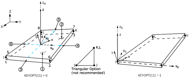
Possible to define 1-direction out of element plane.
. The 4-node elements require a much finer mesh than the 8-node elements to give convergent displacements and stresses in models involving out-of-plane bending. PLANE182 is used to model 2-D solid structures. In addition to 3-D shell elements axisymmetric shell elements are available for efficiently modeling axisymmetric shell structures in 2-D.
A simple modification method employing an effective shear strain concept is introduced to improve the out-of-plane performance of the layered shell. 731 Element Axes Up. Similarly these analyses illustrate the use of shell element S4 for bending in the plane of the element.
Axisymmetric shell elements such as SHELL208 and SHELL209 may include out-of-plane translational degrees of freedom to model uniform torsion about the axis. The transverse shear strains and are forced to be constant in the thickness direction. Plate elements are for out of plane forces.
Couldnt I just use torque and shear force to calculate stress on any line element. The authors employed a layered thick-shell finite element developed on the basis of the Mindlin theory Mindlin 1951 inherently assuming that out-of-plane shear strains are constant through the thickness of the element. A simple model of a wall with a lintel is used and it will be studied the degree of precision of.
When there are both in plane and out of plane forces then typically a shell element is used which is a plane stress and a plate element combined together. The element uses a plane-stress formulation that always leads to zero thickness normal stress. In addition the assumed strain field is designed to eliminate artificial stiffening during in-plane bending due to Poissons ratio effects.
The in-plane lamina strains and vary linearly in the thickness direction. Plane stress elements are for in plane forces. In particular the number of elements to be used when modelling a lintel in order to capture the tractions correctly.
In the case of your skins they will impact the expansion inplane by either limiting the expansion if their coefficient is smaller than your core or trying to increase expansion if their expansion coefficient is greater. Since the elements stiffness is fully integrated no spurious membrane or bending zero energy modes exist and no membrane or bending mode hourglass stabilization is used. Up to 7 cash back Shell elements are 4- to 8-node isoparametric quadrilaterals or 3- to 6-node triangular elements in any 3-D orientation.
Out of plane stiffness of the slab will not be accounted in the analysis wherein reality the structural slab also exists Conventional RC Beam-Slab Structures in a building. In general the use of beam or shell elements with out-of-plane bending is recommended for thin structures. In Abaqus shell element S4 uses an assumed strain treatment for its membrane response that is designed to eliminate parasitic shear stresses that occur when the element is subjected to in-plane bending.
726 Linear Elastic Material Contents Index 73 Plates and Shells. Material Orientation in 2D shell elements. The shells must be concrete and the model must include design combos to take advantage of this feature fully.
Mechanical cover for the shells should also be. Think of balloons for example. Plate or shell structures with a thickness that is relatively small compared to the in-plane dimensions and with out-of-plane loadings may.
NASTRAN doesnt output shear stress for line elements probably for a very good reason Im not privy to. In this article we will study the bending when we model beams lintels with shell elements. But you can get max combined stress as an output which is the sum of axial stress plus bending stress at either of Ends A or B.
Since the actual transverse shearing stresses and strains vary parabolically over the thickness the shearing strains are an. These analyses illustrate the use of continuum elements to simulate bending behavior of thin structures. Curved shell elements characteristics.
However a standard displacement formulation for the out-of-plane bending stiffness is not subject. Even though the word shell in structural mechanics refers to membrane stresses in FEA shell elements normally can take both in plane and out of plane forces. Library of Finite Previous.
Ered out-of-plane shear forces. Shell elements have six DOF per node. Polak and Vecchio 1993 later modified the thick-shell finite-element.
The pressure must be applied directly to the shell and not via surface elements SURFnnn. For shell elements that are primarily subject to out of plane bending Ram Elements can provide output for the area of steel required in the two principal directions per ACI 318-05. Figure 1 shows some typical shell elements.
These ratios relate the expansion of your structure for inplane and out-of-plane directions. Element S4 is a fully integrated finite-membrane-strain shell element. Possible to define 1-direction out of element plane.
Excluding the out of plane stiffness of the slab in the analysis the results such as Bending Moments Shear Forces etc. Will be much higher when we go with the slab. In-plane bending with Shell elements.
It can be used as either a plane element plane stress plane strain or generalized plane strain or an axisymmetric element with or without torsion. Two DOFs are in-plane translations and one DOF corresponds to the out of plane rotation. The analysis procedure is implemented within the framework of a finite-element program employing layered thick-shell elements that consider out-of-plane through-thickness shear deformations.
Even though the word shell in structural mechanics refers to membrane stresses in FEA shell. With KEYOPT10 1 Sz is independently recovered during the element solution output from the applied pressure load. - Material Orientation in 2D shell elements.
- Altair HyperMesh - Altair Products.

Bending Of Closed Thin Inflatable Cylindrical Shell Column Filled With Air Fea Tutorial Finite Element Analysis Tutorial Inflatable

Airplane Silhouette Passenger Plane Landing Back Front 974699 Elements Design Bundles In 2022 Airplane Silhouette Plane Silhouette Passenger Planes

Fairchild C 82 Packet Paratrooper Wwii Aircraft Airborne Army

Can We Use Shell Element Instead Of Plane Stress Element

Basic Elements Lines Colors Values Textures Shapes And Space Formal Elements Of Art Elements Of Art Principles Of Design

Airplane Path In Dotted Line Shape Route Of Plane Isolated On White Background Spon Line Shape Dotted Airp Dotted Line White Background Background

Solidworks Practice Exercise 08 Blower Fan Modeling Solidworks Exercise Tutorial

Travel Tattoo Palm Tree Wave Lotus Line Drawing Artwork Perfect For Small Tiny Tattoo Idea Tiny Tattoos Travel Tattoo Shell Tattoos

1970s Shell Ads By Peter Hutton Vintage Airliners In 2021 Vintage Airline Ads Canadian Airlines Pacific Airlines

Pin On Finite Element Analysis

Fea In Abaqus Tutorial Buckling And Post Buckling Analysis Of Thin Cylindrical Shell Abaqus Finite Element Analysis Analysis

Pin On Charts Graphs Infographics

Sketchbook Vermilion Wlad Zbrush Tutorial 3d Modeling Tutorial 3d Tutorial

Pin On Finite Element Analysis

Pin On Vietnam U S War

Twa Lockheed Super Constellation L 1049 Lego Plane Lego Lego Cars
Shell181

Airplane Passengers Flight Ad Ad Ad Flight Passengers Airplane Passenger Photo Design Background Design

Sunset From The Cockpit Night Sky Illumination Devices Affiliate Night Cockpit Sunset Devices Illumination Ad Cockpit Night Skies Sunset


